Introducing the fascinating world of the Controller Area Network (CAN) bus, the central nervous system of contemporary industrial and automotive communication.
In the 1980s, Robert Bosch GmbH developed it. A Controller Area Network (CAN) bus is a communication system for vehicle-to-vehicle intercommunication.
With the help of this bus, numerous microcontrollers and other kinds of devices can connect instantly and without the need for a host computer.
The Controller Area Network’s reach extends beyond communications between vehicles.
According to a verified market report, the CAN Bus Device Market was estimated at USD 10.3 billion in 2023 and is expected to expand at a compound annual growth rate (CAGR) of 12.6% to reach USD 15.5 billion by 2030.
The CAN Bus Device Market is the area of the automotive industry focused on the production, promotion, and distribution of goods that utilize Controller Area Network (CAN) bus technology.
The CAN bus is a common communication protocol that allows different electronic control units (ECUs) in an automobile to communicate with one another without the use of a host computer.
Its reliable and efficient communication qualities are the reason it is widely employed in modern cars.
In this blog post, we cover all you need to know about the Controller Area Network (CAN) bus. Now let’s explore the entire blog!
What Does Controller Area Network (CAN) Mean?
A communication system called the Controller Area Network (CAN) enables the connection of different electronic equipment in a car.
The message-based Controller Area Network (CAN bus) protocol was created to provide dependable, priority-driven communication between the Electronic Control Units (ECUs) present in modern cars and other equipment.
A Controller Area Network (CAN) is a serial half duplex and differential two-wired asynchronous communication protocol that allows the microcontrollers and other devices to communicate without a host computer.
The CAN core is a bus controller that performs communication according to the CAN 2.0B, and CAN FD specifications according to ISO 11898-1.
There is no need for a host computer because all of the devices in the network can receive messages, or “frames.” Under ISO 11898, CAN is backed by a wide range of international standards.
The Evolution of CAN Bus
Here’s a quick look at the key historical events that played a role in the development of CAN bus technology:
1983: The development of the CAN bus protocol began at Robert Bosch GmbH.
1986: The protocol was officially introduced at the Society of Automotive Engineers (SAE) conference in Detroit, Michigan.
1987: The first CAN controller chips were released by Intel, followed by Philips shortly thereafter.
1991: The Mercedes-Benz W140 became the first production vehicle to feature a CAN-based multiplex wiring system. Bosch also released the CAN 2.0 specification, which consists of two parts:
- Part A: Standard format with an 11-bit identifier (CAN 2.0A)
- Part B: Extended format with a 29-bit identifier (CAN 2.0B)
1993: The International Organization for Standardization (ISO) released the CAN standard ISO 11898, which was later restructured into:
- ISO 11898-1: Data link layer.
- ISO 11898-2: CAN physical layer for high-speed communication.
- ISO 11898-3: CAN physical layer for low-speed, fault-tolerant communication.
2012: Bosch released CAN FD 1.0, or CAN with Flexible Data Rate. This version introduced a new frame format with the ability to handle a larger data length and switch to a faster bit rate after arbitration. CAN FD is fully compatible with existing CAN 2.0 networks, allowing devices supporting CAN FD to coexist with CAN 2.0 devices.
2018: Bosch continued to refine and extend the CAN standards, actively working on improvements.
How Does a CAN Bus Work?
One protocol for decentralized communication is the CAN bus. Its decentralized design makes it perfect for industrial and automotive applications where real-time performance and dependability are crucial.
Twisted-pair wiring or optical fiber cables are used to connect each node in a CAN network. Every node is equipped with a microcontroller that handles receiving and transmitting messages.
A node on the shared bus broadcasts data so that other nodes can receive it.
The primary stages of the communication process are:
- Arbitration: CAN use an arbitration method based on message priority to prevent collisions when numerous nodes attempt to transmit simultaneously. A message’s priority increases with a decreasing identifier value.
- Error detection: Data integrity in CAN networks is guaranteed by integrated error detection algorithms. These consist of frame check sequences (FCS), acknowledgment bits from receiving nodes, and cyclic redundancy checks (CRC).
- Fault confinement: Any node that identifies a problem or malfunctions during transmission will go into a state known as “error passive” until it can function normally again. This keeps malfunctioning communications from interfering with the general operation of the system.
CAN buses can maintain high-efficiency levels and dependable communication between many components in complex systems, such as factory automation equipment or vehicles, thanks to this combination of qualities.
Modern CAN Bus
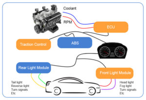
Two wires are used by CAN Bus systems to transfer data between modules on a “bus.”
A bus is a group of modules connected by wiring that is interconnected. There are two buses in the above case.
Separate ones are used for the engine and stability control system and the light modules.
Several buses for different subsystems can be found in modern autos. For instance, there is no need to run the additional wiring because the lighting module does not need to know the engine’s RPM.
An example of a bus system in the real world would be the USB (Universal Serial Bus) hub seen on computers. A single cable can be used to connect multiple devices to a computer.
CAN Benefits
Low-cost, Lightweight Network
Multi-CAN device communication is facilitated via CAN, which offers a robust, low-cost network.
Having a single CAN interface for electronic control units (ECUs) instead of analog and digital inputs for each component in the system is advantageous.
Cars have become lighter and less expensive overall as a result.
Broadcast Communication
All of the network’s devices are intelligent since they are equipped with CAN controller chips. Every device on the network can see every message that is sent.
Every gadget is capable of determining if a communication needs to be filtered or is relevant. With this framework, changes to CAN networks can be made with little effect.
It is possible to add more non-transmitting nodes to the network without changing anything.
Priority
Each message has a priority, so if two nodes attempt to send a message at the same time, the message with the higher priority gets through while the message with the lower priority is delayed.
Transmission of the highest priority message proceeds uninterrupted as a result of this non-destructive arbitration. Additionally, networks can adhere to deterministic time requirements.
Error Capabilities
A Cyclic Redundancy Code (CRC), which is part of the CAN specification, is used to check each frame’s contents for errors.
All nodes ignore frames that include errors, and the network can be informed of the error by transmitting an error frame.
The controller distinguishes between global and local faults, and if an excessive number of errors are identified, individual nodes have the option to either cease transmitting errors or entirely disconnect from the network.

CAN networks significantly reduce wiring
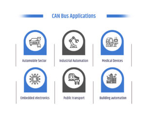
CAN Bus Applications
CAN protocol is widely used by all types of Motor industry applications like passenger vehicles, heavy goods and utility vehicles, and agricultural vehicles.
Being a robust, reliable, and versatile serial communication protocol, CAN is not just limited to automobiles.
Some of the common applications:
- Control modules of high-speed trains and aircraft.
- Entertainment and infotainment systems in automobiles
- Controlling and Monitoring cranes, drilling probes
- Elevators, and lift control systems.
- Building automation like heating and air-conditioning systems
- Automatic doors and curtain openers.
- Automated watering in glasshouses and farms.
- Medical instrumentation due to its robustness and versatility.
- Many machine tool control systems use the CAN network as an in-device bus system enabling factory automation.
- Sensor networks where signal robustness due to environmental factors is required.
Now, let’s see a brief explanation of its applications
CAN in automobiles
Most passenger automobiles employ the CAN protocol, which was developed for in-car networks. It permits data exchange without the need for one-to-one connectivity between many ECUs.
An engine management system based on CAN is found in most autos. Furthermore, the majority of automobiles use CAN-based multiplex systems to connect all of the body electronics and ECUs.
The CAN bus is used to connect the in-car entertainment systems. Aside from that, in-car diagnostic systems make use of the CAN bus.
A specification for CAN-based diagnostic interfaces is ISO-15765. Additionally, connection-oriented data exchange between in-car entertainment systems makes use of the CAN.
The CAN network has an unexpectedly larger role in electric and hybrid automobiles. It helps servo motor controllers, battery management systems, and inverters communicate.
Additionally, it links the driver’s human-machine interface to servo controls.
CAN in public transport systems
In both aircraft and high-speed trains, the CAN protocol is frequently employed. Brake control systems on trains are connected via CAN.
Automatic braking in high-speed trains is enabled with the use of CAN.
Additionally, trains employ CAN to interface with gateways at train bus systems as well as subsystems like door control, diagnostics, brake control, and freight car monitoring.
Automating passenger information systems and customer services is another application for CAN.
CAN-based sensor networks are used in road transportation for traffic monitoring, speed detection, and traffic signal control.
Electronic equipment utilized in nautical environments also uses the CAN protocol. Additionally, it is utilized to link flight status sensors, navigation systems, and aircraft engine control systems.
CAN for industrial automation
Industrial machine control commonly uses CAN-based protocols such as CANopen, DeviceNet, and Smart Distributed Systems, which are robust serial communication protocols with error detection techniques, strong signal logic, and fault containment capabilities.
Embedded CAN networks are used in semiconductor manufacturing equipment, carton packaging machines, textile processing machines, printing machines, and quality control machinery.
Automating production lines and controlling robots are common uses for CAN-based distributed control systems.
CAN in building automation
Sub-networks in building automation use the CAN protocol extensively.
CAN-based protocols facilitate communication between electronic devices from many domains.
These domains include elevator and lift control systems, air conditioning systems, automatic doors, automated curtain openers, window shade control systems, heating and cooling systems, and lighting control systems.
CAN in medical electronics
CAN is a commonly used protocol for in-device communication in medical electronic equipment such as CT scanners and X-ray machines.
This is because of its cross-domain communication capabilities, error-detection ability, and robust signals.
Moreover, inter-device networking in operating rooms and critical care units uses CAN-based protocols.
CAN in embedded electronics
Numerous consumer products and gadgets, including coffee makers, washing machines, vending machines, audio video systems, and many more household appliances, use CAN as a system bus to enable flexible embedded networking.
CAN Protocol
A network of electrical devices connected by a serial bus can be described as using the CAN Protocol, which is a set of guidelines for sending and receiving data.
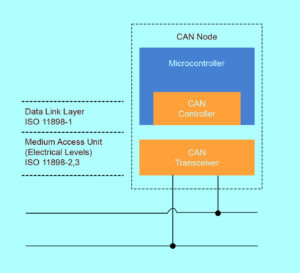
In a CAN network, every electronic equipment is referred to as a node. For data sharing, hardware and software must be integrated into every node.
A host microcontroller unit, CAN controller, and CAN transceiver are components of each node of a CAN bus system.
A CAN controller is a chip that is required to handle data and transfer data via transceiver over the serial bus and vice versa.
It can be inserted individually or integrated into the host controller. Signals are adjusted to CAN bus levels using CAN transceiver chips.
Every message in the message-based CAN protocol has a preset, unique ID.
In a CAN bus network, the transmitted data packet is received by all nodes; however, the CAN node determines whether or not to accept it based on the ID.
If several nodes attempt to transfer data simultaneously, the CAN bus follows the arbitration procedure.
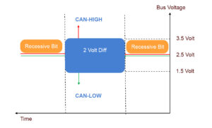
CAN Bus Electrical Specification
The CAN transceiver processes both single-ended and differential CAN signals (CANH and CANL).
In perfect condition, the CAN High and CAN Low lines are at 2.5 volts.
According to CAN, logic “one” is the recessive bit, and logic “zero” is the dominant bit.
The differential voltage of the dominant bit is two volts when it is communicated, with CAN High rising to 3.5 volts and CAN Low falling to 1.5 volts.
CAN High and CAN Low lines are driven to 2.5 volts when the recessive bit is communicated, indicating that the differential voltage of the bit is 0 volts.
To prevent signal reflections, a 120 ohm CAN bus terminal resistor needs to be placed on the physical end of the CANH and CANL lines.
CAN bus differential signals
Frame types of CAN
Frames are predefined data units carried via networks made up of meaningful bytes. There are four types of frames in CAN:
- Data Frame
- Remote Frame
- Error Frame
- Overload frame
Data Frame
The real data for transmission is contained in the data frame.
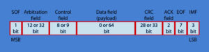
The fields that make up a data frame are the Arbitration Field, Control Field, Data Field, CRC Field, 2-bit Acknowledge Field, and End of Frame. These fields offer more information about the transmission.
There are two types of Data frames
- Standard Frame or Base Frame Format
- Extended Frame Format
The extended frame supports a 29-bit identification made up of an extended 18-bit identifier and an 11-bit identifier, while the normal frame only supports an 11-bit identifier.
In an extended frame, the IDE bit is recessive and dominant in a standard frame.
Base Frame Format
The Base frame format is another name for the standard CAN protocol. Sending data is the primary use of the standard frame.

Standard Frame Terminologies
- SOF – Start of Frame. Denotes the start of frame transmission.
- Identifier – 11-bit unique ID and also represents message priority Lower the value, the higher the priority.
- RTR – Remote Transmission Request. It is dominant for data frames and recessive for remote frames.
- IDE – Single Identification Extension. It is dominant for standard frames and recessive for extended frames.
- R0 – reserved bit.
- DLC – Data Length Code. Defines the length of the data being sent. It is of 4-bit size.
- Data – The data to be transmitted and its length is decided by DLC.
- CRC– Cyclic Redundancy Check. It contains the checksum of the preceding application data for error detection.
- ACK– Acknowledge. It is 2 bits in length. It is dominant if an accurate message is received.
- EOF– end of the frame and must be recessive.
- IFS– Inter Frame Space. It contains the time required by the controller to move a correctly received frame to its proper position.
Extended Frame

Extended Frame
It is the same as the Standard Frame with some additional fields.
SRR- Substitute Reverse Request.
If both messages have the same 11-bit identifier, the SRR bit is always broadcast as a recessive bit to guarantee that the regular Data frame has a higher priority than the extended Data frame.
In addition, it has an 18-bit identification rather than only an 11-bit one.
Remote Frame
With two exceptions, the remote frame is comparable to a data frame. The receiver sends the distant frame to the transmitter to request data.
The distant frame and the data frame vary in that the former does not include any data fields because it is not intended for data transport.
The second distinction is that the arbitration field’s RTR bit is recessive for distant frames.
Because of the dominant RTR bit in the data frame, the data frame wins the arbitration if both are prepared to be broadcast simultaneously.
Error frames
The transmission will cease instantly.
An error frame including an error flag composed of six dominant bits and an error flag delimiter composed of eight recessive bits will be sent.
This will occur if either the transmitting or receiving nodes identify an error.
Error flags
- Active Error flag
- Passive Error flag
Active Error Flag- Transmitted by the node when an error is detected on a CAN network
Passive error flag – Transmitted by the node when an active error is detected on a CAN network.
Error Counters – If an error is detected on a bus, then the TEC or REC count increases.
- Transmit Error Counter (TEC)
- Receive Error Counter (REC)
- When TEC and REC are less than 128, an active error frame is transmitted
- When TEC or REC is greater than 127 and less than 255, a passive frame is transmitted
- When TEC is greater than 255, the node enters into bus off state, then no frames can be transmitted
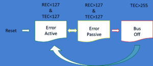
Error Transition State Diagram
Overload Frame
The two fields, Overload Flag and Overload Delimiter are part of the overload frame. Six dominating bits make up the overload flag, which is followed by overload flags produced by additional nodes. There are eight recessive bits in the overload delimiter. The following overload scenarios result in the sending of an overload frame:
- when the receiver requires time for the next frame.
- when a dominant bit is detected during intermission.
Key Components within a CAN Bus System
The key components that form the core of a CAN Bus system, ensure its efficient and reliable operation.
- Electronic Control Units (ECUs): The ‘brains’ of the CAN Bus, or ECUs, are responsible for regulating certain operations like airbag activation and engine management in cars. They receive data over the CAN Bus, process it, and take appropriate action.
- CAN Controller: This part serves as a link between the CAN network and the ECUs. It oversees the sending and receiving of data packets, making sure that messages are sent and structured correctly.
- CAN Transceiver: The CAN Transceiver transforms digital data into signals for network transmission with the CAN Controller, and vice versa. This is necessary for node-to-node communication within the network.
- Bus Lines (CAN_H and CAN_L Wires): The CAN Bus system is supported by the physical wires known as CAN_H and CAN_L. Even in settings with a lot of electrical noise, they send signals between nodes.
When combined, these parts guarantee the CAN Bus system’s dependable and effective performance in a range of contexts, including industrial and automotive applications.
CAN Physical Layers
There are multiple physical layers available for use in CAN.
Aspects of the CAN network such as electrical levels, signaling systems, cable impedance, maximum baud rates, and more are classified by these physical layers.
The following is a description of the physical layers that are most frequently used:
High-Speed/FD CAN
By far the most popular physical layer is high-speed CAN.
High-speed CAN networks can communicate at up to 1 Mbit/s when they are implemented using two wires. High-speed CAN is also known as ISO 11898-2 and CAN C.
Engine control modules, emissions systems, and antilock brake systems are examples of common high-speed CAN devices.
The next iteration of high-speed CAN communication, known as CAN with Flexible data rate (CAN FD), features growing standards for higher data rates.
Low-Speed/Fault-Tolerant CAN Hardware
Two wires are also used to build low-speed/fault-tolerant CAN networks, which can connect with devices at up to 125 kbit/s and provide transceivers with fault-tolerant features.
CAN B and ISO 11898-3 are other names for low-speed/fault-tolerant CAN. Comfort devices are typical examples of low-speed/fault-tolerant devices in an automobile.
Due to the inherent stress of opening and shutting a door puts stress on cables, those that must travel through a car’s door are low-speed/fault-tolerant.
In addition, low-speed/fault-tolerant CAN provides a solution where a higher degree of security is required, like with brake lights.
Single-Wire CAN Hardware
Devices can communicate with single-wire CAN interfaces at up to 33.3 kbit/s (88.3 kbit/s in high-speed mode).
Single-wire CAN is also known as GMLAN, CAN A, and SAE-J2411. Standard single-wire electronics in a car don’t need to be very efficient.
Comfort equipment like seat and mirror adjustments are frequently used.
Software-Selectable CAN Hardware
Software-selectable CAN interfaces can be configured to use any of the onboard transceivers (high-speed, low-speed/fault-tolerant, or single-wire CAN) using National Instruments CAN hardware products.
For applications requiring a variety of communications standards, multiple-transceiver hardware provides the ideal answer.
You have more control over the external CAN transceiver when using software-selectable CAN hardware.
Variations of the CAN bus
The ISO 11898 standard defines several versions of CAN. The dominant CAN types used within the automobile industry are:
- Low-Speed CAN
- High-Speed CAN
- CAN FD (Flexible Data Rate CAN)
Low-speed CAN
Utilized in systems that do not need high update rates and are fault-tolerant.
Although the wire is less expensive than high-speed CAN, the maximum data transfer rate is 125 kbps.
Low-speed CAN is utilized for power windows, dashboard controls and displays, diagnostics, and other automobile applications.
High-speed CAN
Used for communications between vital subsystems (engine control units, airbags, electronic stability control, anti-lock brake systems, etc.) that demand fast update rates and excellent data accuracy.
High-speed CAN has a data transport rate of 1 kbit to 1 Mbit per second.
Automobile OEMs are increasingly putting CAN FD in new automobiles because high-speed CAN is quicker than low-speed CAN, yet the bandwidth requirements of new automotive applications are growing annually.
It has been mockingly referred to as “CAN on steroids” for CAN FD.
CAN FD (flexible data rate CAN)
More data per message, substantially faster transmission speeds, and a configurable data rate are all features of the most recent CAN version.
With CAN FD, the 8 bytes of data that make up conventional CAN communication (low speed and high speed) are extended by 800% to 64 bytes.
The maximum data rate has also been significantly raised from 1 Mbps to 8 Mbps.
CAN FD data frame format
In addition to being backward compatible, CAN FD supports the CAN 2.0 communication protocol and unique protocols like SAE J1939, which uses CAN out as read-only.
All classical CAN systems are fully compatible with CAN FD, which is an expansion of the original CAN standard as described in ISO 11898-1.
CAN FD represent a significant advancement as it enables ECUs to adjust their transmission rates and message sizes dynamically in response to real-time demands.
Although it is now only found in high-performance cars, it won’t be long before CAN FD is present in almost every car due to improvements in ECU performance and a decline in the cost of CAN FD hardware.
The Future of CAN Bus & Conclusion
In the future, the CAN bus protocol will still be very important, but it will be impacted by the following major trends:
- Increasingly advanced vehicle functionality: Vehicles will need to have more advanced communication systems.
- Impact of cloud computing: The development of cloud computing will have an impact on how cars and outside services communicate.
- Growth in IoT and connected vehicles: The growth of IoT CAN loggers and car telematics will be fueled by the Internet of Things (IoT).
- Adaptation to autonomous vehicles: The CAN bus may need to change in the future to meet the specific needs of autonomous vehicles as they become more common.
In conclusion, the adoption of the Controller Area Network (CAN) bus has brought about a dramatic transformation in the automotive, health, and industrial sectors.
This is due to the several important benefits that this technology offers, including resilience, quick access, simplified communication, and efficient data prioritizing.
The CAN bus is still a vital instrument for reliable and smooth communication between machines and automobiles as our reliance on cutting-edge technologies grows.
Frequently Asked Questions (FAQs)
How does a CAN bus system work?
Data is transmitted over a twisted pair of wires using the differential signaling system by the asynchronous serial communication protocol known as CAN Bus.
It makes use of a message-based communication paradigm in which each connected device can send and receive data frames, which are messages.
How many types of CAN buses are there?
The three primary CAN Bus module types high-speed, low-speed, and CAN Flexible Data Rate (CAN FD) will be discussed in this section.
What is CAN bus protocol?
The ISO 11898 standards define a controller area network as an electronic communication bus.
These standards specify, among other things, how wiring is set up, how communication takes place, and how messages are put together. This system is referred to as a CAN bus together.
How many nodes CAN a CAN bus have?
On a CAN bus, the maximum number of nodes is usually 32, but the actual number depends on the properties of the physical layer that is being used.
Depending on the number of bytes in each message, the maximum number of messages per second on a bus with a 250 KBaud transmission rate is between 2000 and 5000.
What is the working principle of the CAN bus?
Any device connected to a CAN bus can generate a “data frame,” which is the common message structure, and send it sequentially.
When multiple devices communicate simultaneously, the device with the greatest priority sends first and the others wait.